MISCELLANEOUS
Mechanical equipment of clarifiers
Mechanism of slimesettlers cleaning
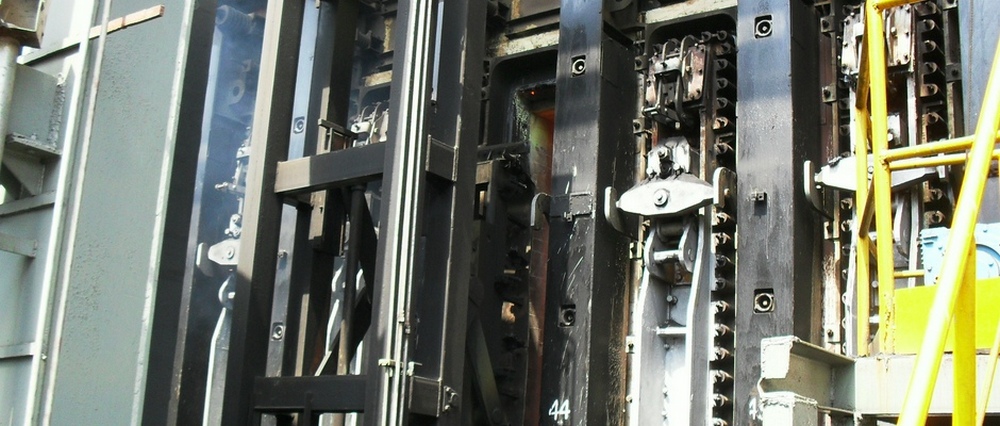
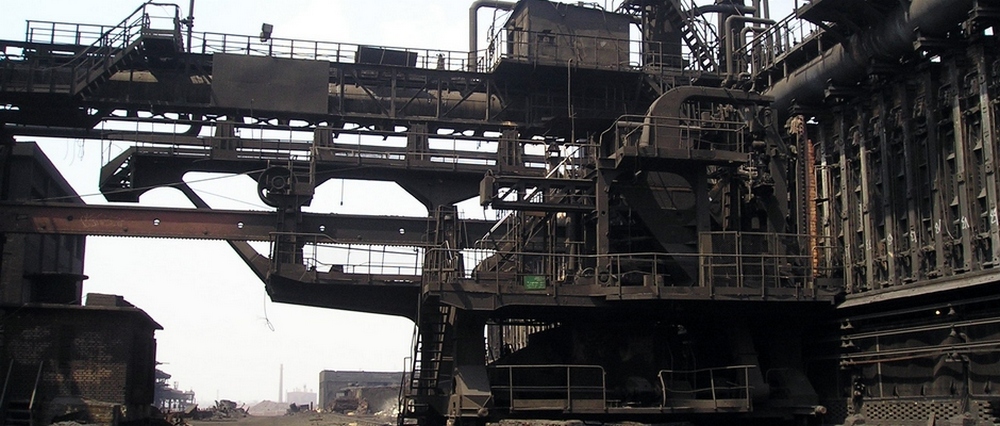
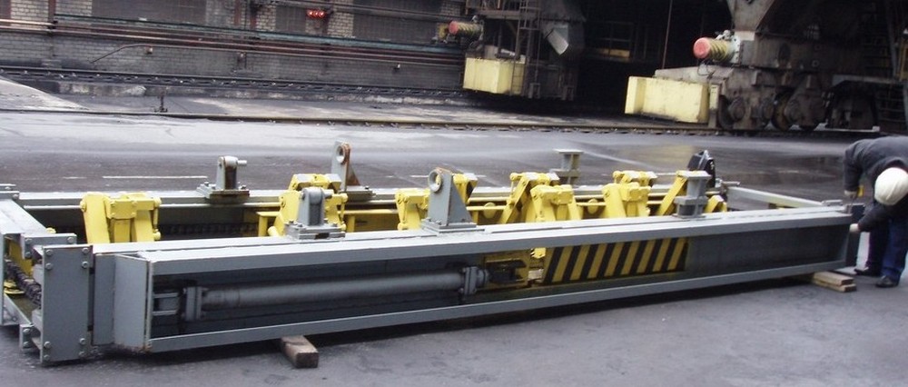
Mechanical equipment of clarifiers
Mechanical equipment of clarifier is supplied for complete set mechanized clarifier of ammonia-tar water of volume 210, 380, 650 m3.
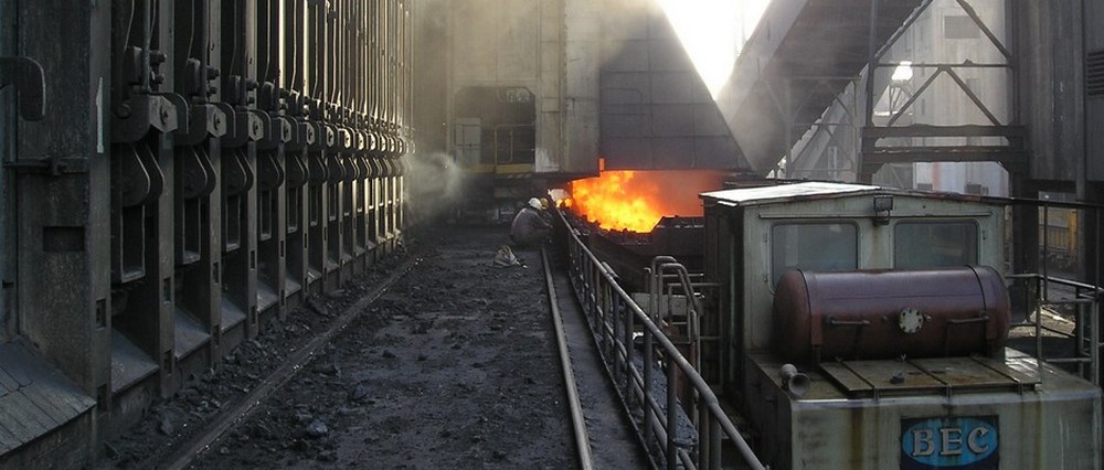
Mechanized clarifier is designed for separation liquid mixture of water, tar and heavy coal-tar products, which are supplied from gas collecting mains of coke oven batteries, and mechanized removal of heavy coal-tar products (foots).
Mechanical equipment of clarifier consists of drive, scraper conveyor, slide gate, reverse device and lever controller.
Equipment is intended for operation in open air in the conditions of aggressive medium of coke-making production. Equipment is used in clarifiers of rectangular and round shapes.
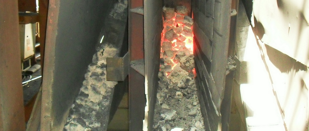
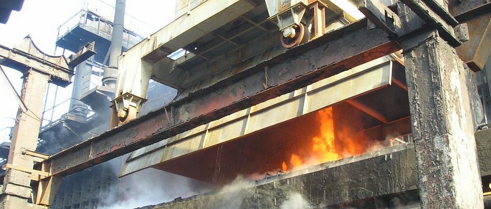
Mechanism of slimesettlers cleaning
Mechanism is designed for mechanized intake of slime from settler of quenching towers and its transportation to the place of discharging.
Mechanism, represented by jib crane, swiveling (or nonswiveling) grab crane on railway travel with rope-block drive of traveling from pulling winch, is proposed. Jib with rope-block drive of traveling accessory (for intake, lifting and discharging of slime) is installed on slewing platform (or on the frame of mechanism directly). Mechanism has two traveling bogies, horizontal and vertical balancers, and also mechanisms for weight lifting, closing of dipper and swiveling. All drives of mechanisms are electromechanical. Remote control of mechanisms is also provided.
Technical features
| Total lifting capacity, t | 3,0 |
| Including dipper, t | 1,5 |
| Design capacity, kW | 60 |
| Control | remote |
| Weight with balancers, kg | 40000 |
Compact plain-sleeve filter
The filter is designed for collection of dust from gas medium, supplied for cleaning after technological apparatus. It is applied in aspiration systems of industry with nonadhesive components of dust.
Sleeve filter consists of body, hopper, screw conveyor, slide gate, blow-off fan, regeneration carriage, gap bridge, plain filtering elements.
The filter operates in the following manner: cleaned gas under action of negative pressure, originated by smoke exhauster of aspiration unit, is supplied into the body, to chamber of precleaning, where partial dedust from great particles of dust is performed due to sharp reduction of gas flow speed. Great dust is settled into hopper and outputted from it by screw conveyor to dust removal system.
Previously dedusted gas distributed uniformly on plain-filter element. Gas is dedusted completely when it transfers through filter material. Then the gas is supplied to chamber of cleaned gas through open ends of plain filter element. After that the cleaned gas is sucked by exhauster and dropped to the atmosphere. Hydraulic resisting of filter rises while accumulating of dust on outer surface of plain filter element. Filter material of plain filter element shall be regenerated by cleaning.
This can be done by the following way: Blowing carriage is moved along gap bridge and time to time stopped on each vertical row of plain filter element. Air, pressurized by blow-off fan which create three air impulses for the period of regeneration of one row, is supplied to blow element of carriage through slide gate and flexible hose; and then it is fed through outlet-nozzle into opened ends of plain filter element. Herewith in the vertical row of plain filter element the blowing air counter-flow is generated against gas to be cleaned and dust, which has settled on outer surface of filter material, is to be shaken off to hopper.
Design of carriage is executed in such a way, that at regeneration not only the row of plain filter element to be cleaned is covered but adjacent rows. It provides dust being shaken-off from regenerated row of plain filter element is settled into the hopper but not onto adjacent filter elements. After completion of regeneration of one row blowing carriage moves to another row.
Technical features
| Area of filtration, m2 | 240 |
| Air capacity, m3/h | 20000 |
| Maximum temperature of dusted air, °— | 140 |
| Dust weight concentration, g/m: on filter entrance, up to on filter exit, not less than |
20 0,05 |
| Type of filter elements | plain envelope |
| Number of filter elements | 192 (32ı6) |
| Dimensions of filter element, mm | |
| length | 186+20 |
| width | 370+1 |
| thickness | 20 |
| Requirements to regeneration of filter elements: | |
| Type of regeneration | reverse blowing |
| Pressure of blowing air, kPa | 6,0 |
| Time between regenerations, min. | 7 |
| Time for blowing of one vertical row, kPa | 10 |
| Device for dust collecting | screw feeder |
| ÕThe most permissible negative pressure in filter, kPa, not more than | 6,0 |
| The most permissible hydraulic resistance in filter, kPa, not more than | 2,0 |
| Overall dimensions, mm, not more than: | |
| length | 3000 |
| width | 2300 |
| high | 6500 |
| Weight (excluding service platforms), kg | 8000 |
| Type and voltage of current, V | alternating 380+10% +/- 5% |
| Frequency of three-phase current, Hz | 50+0,2 |
Reversing hammer grinder
The grinder is designed for grinding of coal of different grades before cocking for coke-making plant use.
Technical features
| Material to be grinded: coil, compression strength, MPa | 100 |
| Capacity, t/h | 150...300 |
| Size of material piece to be charged, mm, not more than | 80 |
| Size of material piece at the output | 0...3 |
| Class content 0Ö3 mm in grinded product, not less than | 80 |
| Class content 0Ö0.05 mm in grinded product, not more than | 44 |
| Diameter of rotor, mm | 1450 |
| Length of rotor grinding part as per hammers, mm | 1300 |
| Frequency of rotor rotation, r/sec | 16,6 |
| Number of longitudinal row of hammers | 10 |
| Number of hammers, pcs. | 115 |
| Electric motor: type AOK-630-10-1000T1 - power, kW - rotation frequency, r/min - weight, kg |
630 1000 5500 |
| Weight of the grinder (excluding spare parts and electrical part), t | 24,2 |
Description of work:
Coal to be grinded is continuously supplied through chute. Coil is grinded by means of breaking with hammer impacts of rotating rotor and kicking on dash plates. Complete grinding of coil is performed on grate grass. Grinded coil spills through gaps of grate grass partially, and basic mass is dropped through opening on butt of sections of grate grass or through open window of swiveling plate. The grinder can operate at rotor rotation in any direction, so that it extends the service life of fast wearing parts.
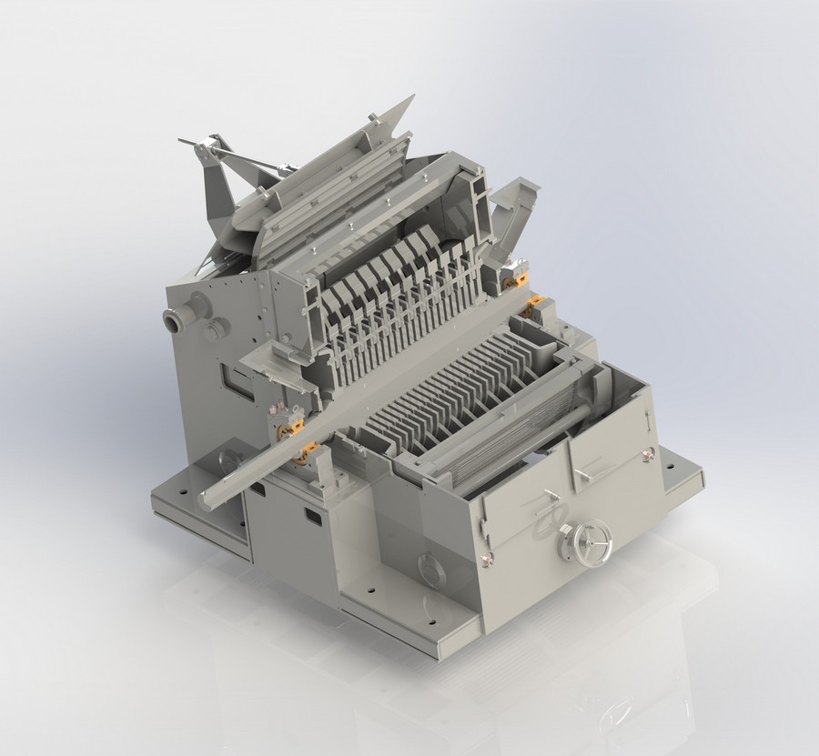
Reversing hammer grinder. Working electronic model.
Moveable mixers
Movable mixer Ãœ-350 is designed for transportation of liquid iron, having the maximum temperature of °— from blast furnaces to steel foundry. It provides the transportation under the minimum heat losses and refining of heat and chemical homogeneity of liquid iron.
Movable mixer consists of body (reservoir), swivel platforms, traveling bogies and the body swiveling mechanism. Body rests on supports executed as a balancers and thrust rollers. Both swiveling platforms are rested on balancers of traveling bogies using spherical bearings. Traveling bogies are equipped with automatic couplers and breking equipment. Design of traveling part of the mixer provides uniform distribution of pressure from each wheel pair. The mixer has required apparatus and two button stations for providing of body swivel in manual mode. The mixer is equipped with system of weighing with possibility of information transfer through radio channel at its filling at blast-furnace plant. Draining of cast iron from the mixer is provided in automatic mode at converter plant.
The mixer is equipped with electric lighting, sound and light signalization, necessary electrical interlocking, inbuilt system of weighing and wireless data transfer about weight of cast iron.
Operational reliability of electrical part is provided using modern solutions and component parts of leading manufacturers. Electrical part of the mixer allows operating in complex with Automatic Control System of a plant.
Technical features
| Nominal load lifting capacity, t (at filling coefficients 0,95...0,98) | 321 |
| Width of railway track gauge, mm | 1520 |
| Maximum load on axle, kN | 500 |
| Traveling speed, km/h, not more than ñ with cast iron (traveling through curves and arrows) ñ with cast iron (traveling along straight way) ñ without cast iron (traveling along straight way) |
5 10 20 |
| Curvature radius in curves of railway track, min., m | 80 |
| Number of axles of running part, pcs. | 16 |
| Swelling angle of reservoir of the mixer, °, max. for complete discharge of cast iron | 180 |
| Time of swelling of reservoir on 180°, min | 1,2 |
| Outside temperature of reservoir, °—, max. | 250 |
| Temperature of liquid metal to be charged, °—, max. | 1440 |
| Temperature of liquid metal to be discharged, °—, max. | 1370 |
| Maximal time of iron storage in the mixer at emergency situation, h | 4 |
| √Overall dimensions, mm: ñ length over axle coupling ñ width ñ height |
30385 3380 4595 |
| Weight of the mixer including lining, t | 315 |
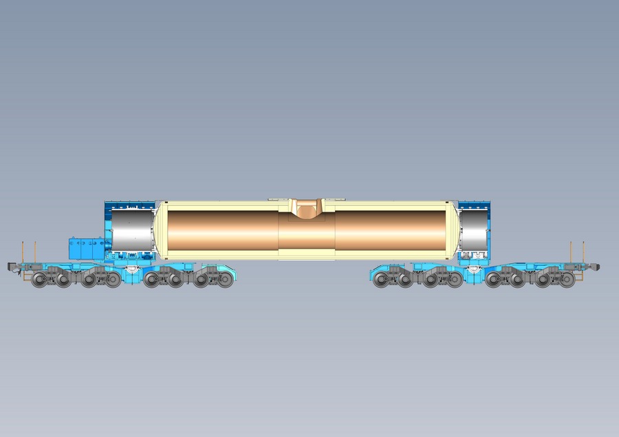
Moveable mixer Ãœ ñ 350 in section.

Moveable mixer Ãœ ñ 350